Circuit
The Circuit panel is the canvas where you assemble your program - quantum and classical registers laid out as horizontal wires, with gates dropped onto them.
Synced with the code panel
Everything you do here is mirrored live in the code panel, and vice versa - edits in OpenQASM, Qiskit, Cirq, or Q# update this canvas instantly, in both directions.
Quantum and classical registers
Every circuit starts with a set of quantum registers (labeled q[0], q[1], ...) and classical registers (labeled c0, c1, ... or grouped, e.g. c6):
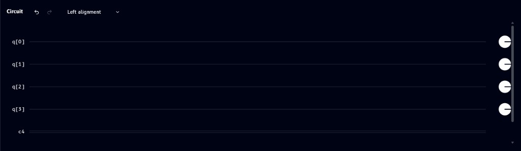
By default, each quantum wire ends in a small circle marker on the right - this is the default measurement/readout marker, shown on every wire whether or not you've explicitly added a measurement operation.
Managing registers
Open Manage registers from the Edit menu to add, rename, resize, or delete registers:
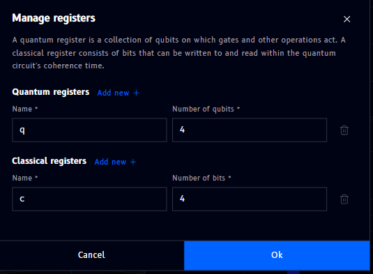
- Quantum registers - set a name and the number of qubits
- Classical registers - set a name and the number of bits
- Click Add new + to create another register of that type
- Click the trash icon to delete a register
- Ok applies changes, Cancel discards them
Dropping operations
Drag a gate from the Operations panel onto a register wire to place it. Once dropped, the gate appears as a colored tile directly on the wire. Not sure what a gate actually does? Every gate has its own page in the Gate reference.
![H gate placed on q[0]](../../../images/circuit/gate-placed.png)
Editing, viewing info, and other gate actions
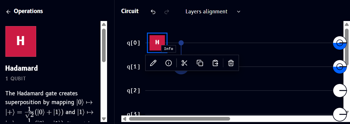
Click a placed gate to select it and reveal a small action toolbar above it:
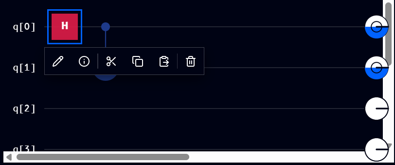
From left to right, the toolbar offers:
| Icon | Action |
|---|---|
| Pencil | Edit the gate (e.g. change a rotation angle) |
| (i) | Info - view details about the gate |
| Scissors | Cut |
| Two overlapping squares | Copy |
| Square with arrow | Paste |
| Trash | Delete |
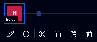
Hovering over an icon shows its label, e.g. hovering the pencil shows Edit:
Gate info panel
Selecting a gate and choosing Info opens details in the Operations panel - the gate's name, how many qubits it acts on, and a description of what it does:
Multi-qubit gate symbols
Some gates span more than one wire and are drawn as connected symbols rather than a single tile. Here's a CNOT, connecting q[1] (control) to q[2] (target):
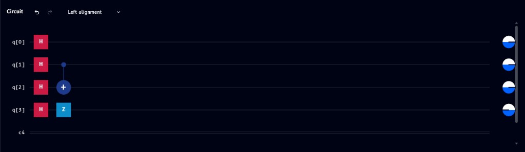
- CNOT - a solid dot on the control wire, connected by a vertical line to a circled + on the target wire
- SWAP - an ✕ mark on each of the two wires being swapped, connected by a vertical line
The same control-dot symbol is also used by Toffoli (two control dots) and by the standalone Control tile for building custom controlled gates.
Alignment modes
The dropdown next to the undo/redo arrows (top of the Circuit panel) controls how gates are laid out:
Left alignment
Gates are moved as far left as their order and multi-qubit connections allow, producing a compact circuit.
Layers alignment
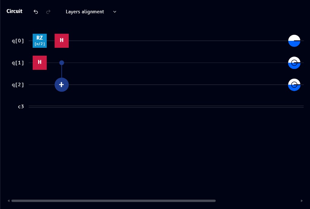
Gates are grouped into vertical execution layers. Gates that can run at the same stage share a column, so the circuit's sequence is easier to read. Unlike Left alignment, this mode prioritizes visible execution stages over using the least horizontal space.
Freeform alignment
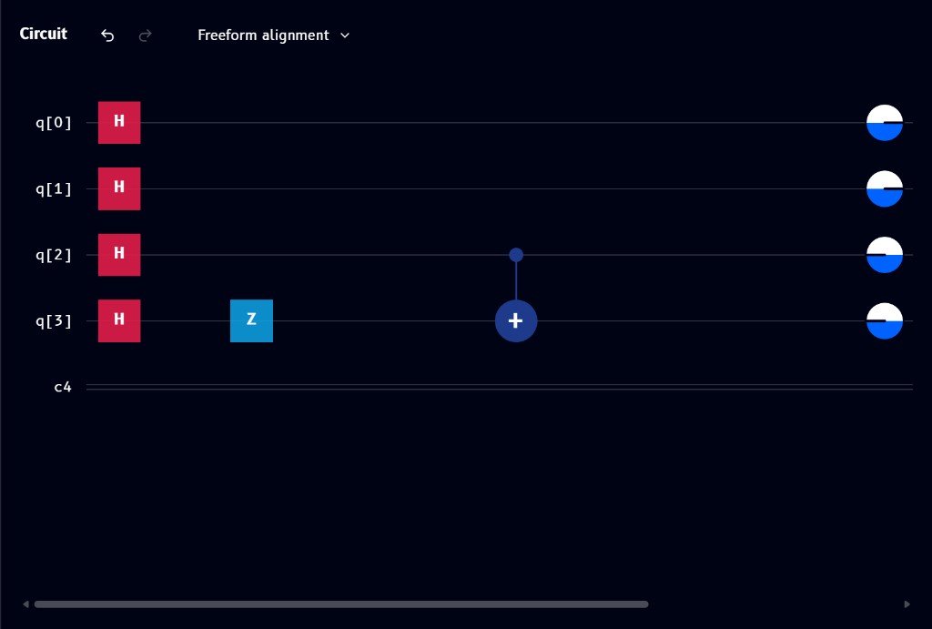
Gates keep their manually chosen horizontal positions instead of snapping left or into layer columns. This gives you full control over spacing and visual layout.
Visualizations seed
Also found under the Edit menu, Visualizations seed controls the randomness used by the Q-Sphere and Statevector plots:
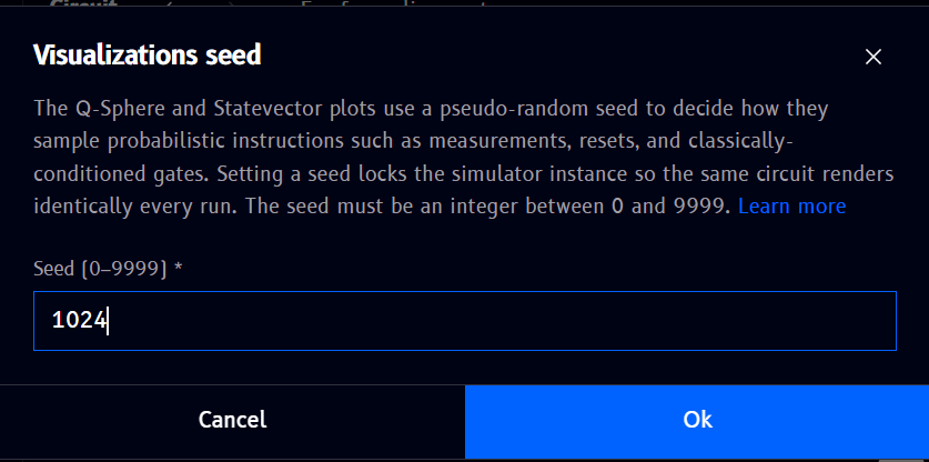
The Q-Sphere and Statevector visualizations use a pseudo-random seed to sample probabilistic instructions such as measurements, resets, and classically-conditioned gates. Setting a seed locks the simulator instance so the same circuit renders identically on every run.
- Enter an integer between 0 and 9999
- Click Ok to apply, or Cancel to discard
Selecting multiple operations
Drag a selection box around several gates (or shift-click each one) to select them together. A dashed bounding box appears around the selection, with its own toolbar:
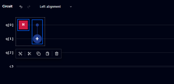
Unlike the single-gate toolbar, this one has no pencil (edit) or info icon - since those don't apply to a multi-gate selection. From left to right: Group, Cut, Copy, Paste, Delete.
Grouping operations
Hovering the first icon in the multi-select toolbar confirms it's Group:
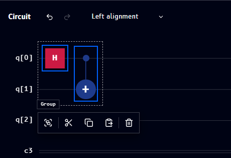
Clicking Group opens a dialog to turn the selection into a reusable custom gate:
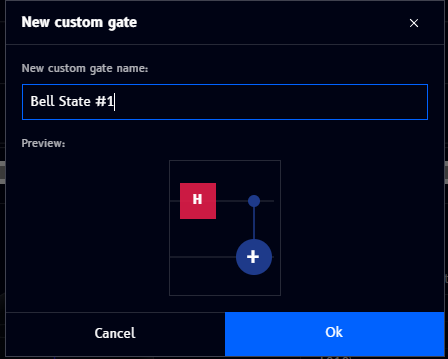
- Enter a name for the new gate (e.g.
Bell State #1) - The Preview shows the sub-circuit being grouped
- Ok creates the gate, Cancel discards it
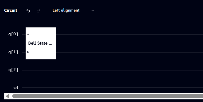
Once created, the grouped gates collapse into a single labeled block on the circuit, with one pin per qubit it acts on (labeled a, b, ...):
Managing custom gates
Custom gates you create also appear in the Operations catalog alongside the built-in gates, so you can drag them onto other circuits. Right-click (or use the equivalent menu) on a custom gate tile to manage it:
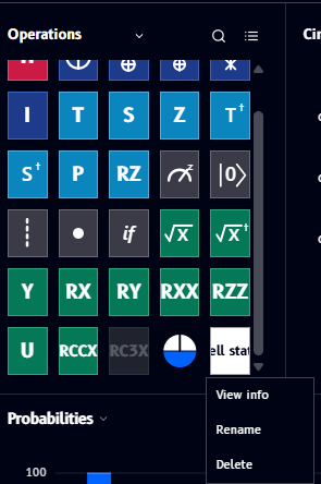
- View info - see details about the custom gate
- Rename - change its name
- Delete - remove it from the catalog
How grouping appears in code
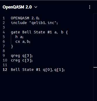
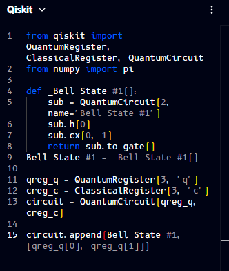
Grouping doesn't just change the diagram - it changes the generated code too, defining the group as a reusable gate/subroutine and then calling it. The same H + CNOT group shown above, across all four languages:
OPENQASM 2.0;
include "qelib1.inc";

gate Bell State #1 a, b {
  h a;
  cx a,b;
}

qreg q[3];
creg c[3];

Bell State #1 q[0],q[1];
from qiskit import QuantumRegister, ClassicalRegister, QuantumCircuit
from numpy import pi

def _Bell State #1():
    sub = QuantumCircuit(2, name='Bell State #1')
    sub.h(0)
    sub.cx(0, 1)
    return sub.to_gate()
Bell State #1 = _Bell State #1()

qreg_q = QuantumRegister(3, 'q')
creg_c = ClassicalRegister(3, 'c')
circuit = QuantumCircuit(qreg_q, creg_c)

circuit.append(Bell State #1, [qreg_q[0], qreg_q[1]])
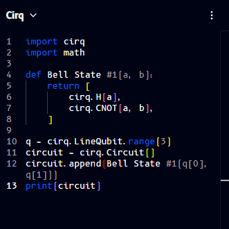
import cirq
import math

def Bell State #1(a, b):
    return [
        cirq.H(a),
        cirq.CNOT(a, b),
    ]

q = cirq.LineQubit.range(3)
circuit = cirq.Circuit()
circuit.append(Bell State #1(q[0], q[1]))
print(circuit)
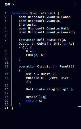
namespace QompileCircuit {
    open Microsoft.Quantum.Canon;
    open Microsoft.Quantum.Intrinsic;
    open Microsoft.Quantum.Math;
    open Microsoft.Quantum.Convert;

    operation Bell State #1(a: Qubit, b: Qubit) : Unit is Adj + Ctl {
        H(a);
        CNOT(a, b);
    }

    operation Circuit() : Result[] {
        use q = Qubit[3];
        mutable c = [Zero, size = 3];

        Bell State #1(q[0], q[1]);

        ResetAll(q);
        return c;
    }
}
Note
The gate name used here (Bell State #1) contains a space and a #, which isn't valid as a literal identifier in real OpenQASM/Qiskit/Cirq/Q# code - Qompile displays the name as typed, but you'd need a code-safe name (e.g. bell_state_1) to actually run this code outside Qompile.
Phase disks (in-circuit)
Phase disks are markers you manually insert at a chosen point on the circuit to snapshot each qubit's relative phase at that moment - distinct from the plain white circle that always sits at the very end of every wire (that's the default measurement/readout marker, see Registers above).
To insert one, drag the phase disk tool from the Operations catalog and click the position on the circuit where you want the snapshot. A dashed vertical divider appears, with one disk per qubit wire showing that qubit's phase at that point, colored using the same Phase wheel used in the Q-Sphere and Statevector panels.
See Phase disks for a full explanation of what phase means, what the disk's color (and its plain white default) represents, and worked examples of inserting one on a Bell-state circuit, both before and after adding measurement gates.
Undo/redo, cut/copy/paste/delete, clear circuit
These are available both from the gate action toolbar above and from the Edit menu - see File / Edit / View dropdowns for the full list and keyboard shortcuts.